
Delivery of the flight model of the VIS instrument Calibration Unit of the Euclid mission
On Monday, March 12th, IAS delivered the flight model of the in-flight calibration system (Calibration Unit, CU) of the VIS instrument of the Euclid mission. Euclid is the M2 mission of the ESA Cosmic Vision programme, whose scientific objective is to map the Universe to explain the cause of the acceleration of its expansion. It will achieve this by looking up to 10 billion years in the past and by closely tracking the shape and distribution of galaxies the Universe contains.
The Euclid telescope will feed the two payload instruments: the NISP (Near Infrared Spectrometer, LAM, France) and VIS (visible instrument, MSSL, United Kingdom). IAS has designed, built and tested the flight calibration system (CU) of the VIS instrument. The goal is to provide a very uniform light beam. The major technical complexity is to achieve a uniformity better than 83% over the entire focal plane, which is 300mm × 360mm, and better than 98% on all local areas of 6mm × 6mm. In addition, the extinction of the beam must be done on a transition zone of less than 13mm in order to limit the stray light in the instrument.
The CU is made of 6 LEDs whose wavelengths cover a spectral range of 590 to 885 nm (visible light and near infrared), producing an image shaped at the exit of the sphere by a mask, a lens and a deflector. Following the flight model CU delivery by IAS, the flight model for the entire VIS instrument will be delivered by the MSSL in November 2019, to be integrated into the Euclid payload. The launch of the mission is scheduled for July 2022 aboard a Soyuz rocket from Kourou.
The CU realization at IAS is funded by CNES, CNRS, and Université Paris Sud.
Contacts at IAS : Nabila Aghanim (science), Anne Philippon (engineering)
https://euclid.cnes.fr/fr/EUCLID/Fr/GP_mission.htm
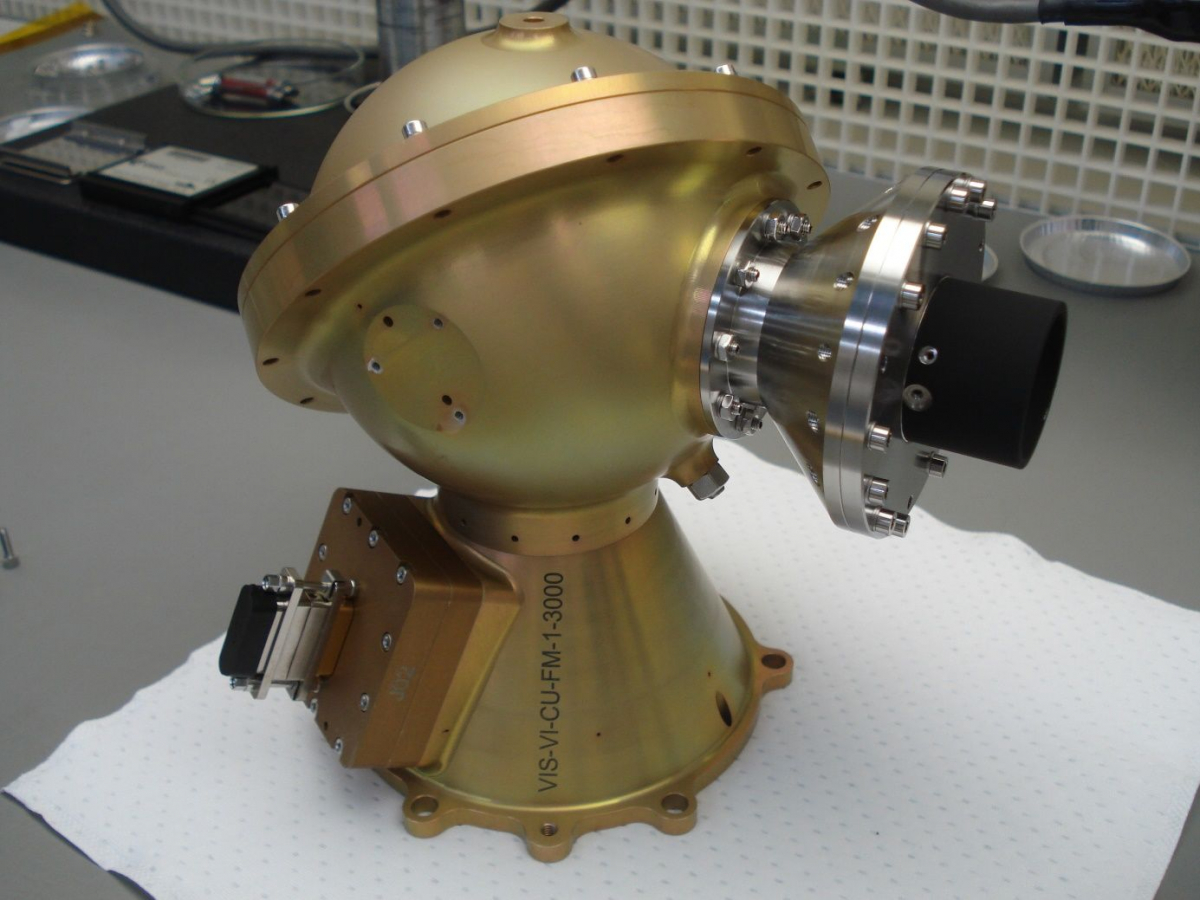
Fig. 1 : Flight model Calibration Unit (CU), after integration (©IAS)
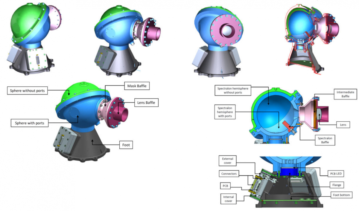
Fig. 2 : Annotated sectional views of the CU
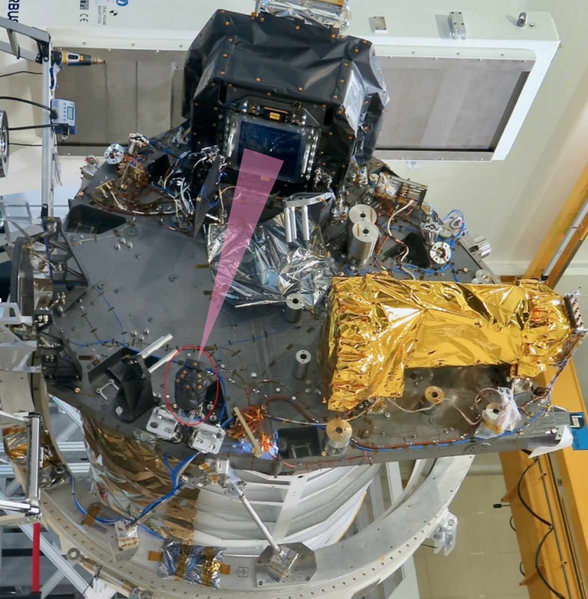
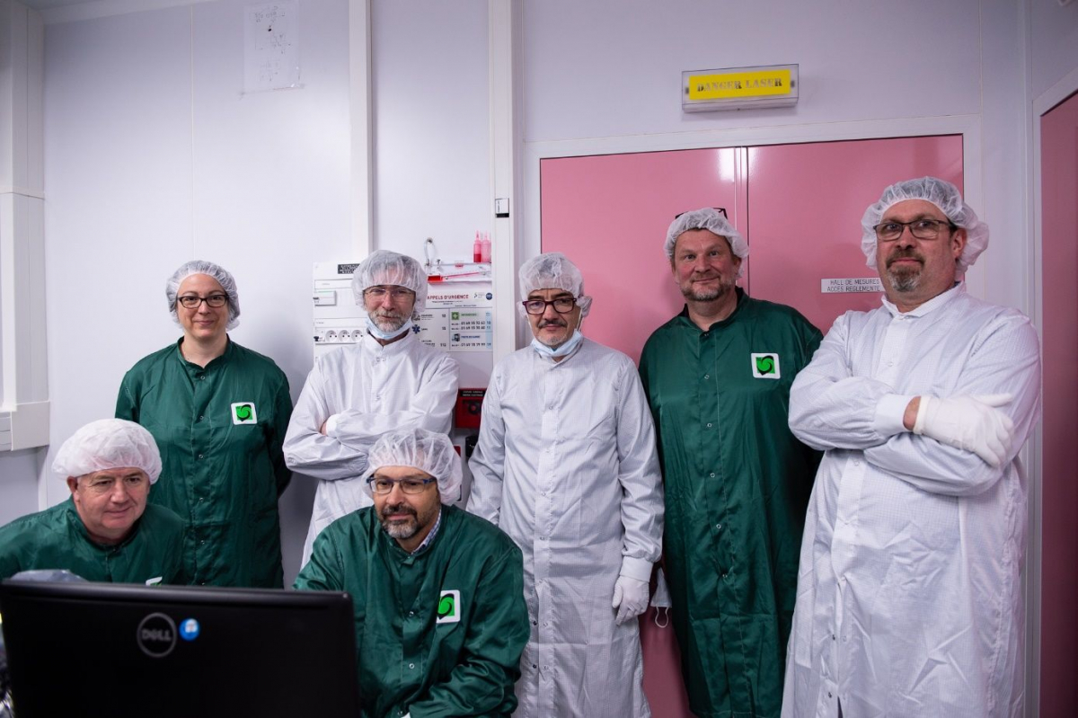
Fig. 4 : A part of the IAS, MSSL, and CEA teams, during the CU (and PMCU) acceptance tests
